I presented a poster titled “A Method of 3D Printing which is Consistent with Natural Direction in Shape”, in SFF Symposium 2013. The poster is not sufficiently self-explanatory, so a more self-explanetory version is presented here.
Abstract: Usually, objects are horizontally sliced when printed by 3D printers. Therefore, if an object to be printed, such as a collection of fibers, originally have natural direction in shape, the printed direction contradicts with the natural direction. By using proper tools, such as field-oriented 3D paint software, field-oriented solid modelers, field-based tool-path generation software, and non-horizontal FDM 3D printers, the natural direction can be modeled and objects can be printed in a direction that is consistent with the natural direction. This consistence results in embodiment of momentum or force in expressions of the printed object. To achieve this goal, several design and manufacturing problems, but not all, have been solved. An application of this method is (Japanese) 3D calligraphy.
Original poster1. Problem to Solve
An object to be printed, such as a collection of fibers, may have “natural direction” in shape. See Figure 1. A leaf has leaf veins, each of which has a natural direction. Each part of human hair and Chinese or Japanese calligraphy also have a natural direction too.
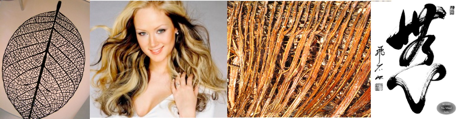
Figure 1. Natural direction in shape
However, the printing direction of fused deposition modeling (FDM) 3D printers, which is most popular in cheaper 3D printers, may contradict with the “natural direction” because the print head always run horizontally. This contradiction causes so-called “staircase effiect”, and both the shape and the intensity of the printed object are not good. See the left half of Figure 2. The shape should be similar to the right half of Figure 2.
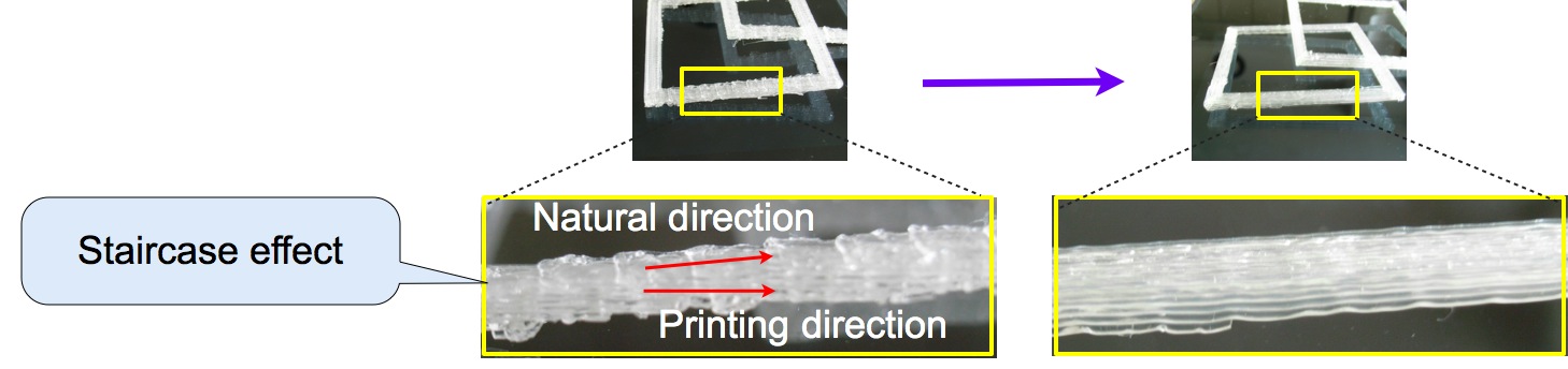
Figure 2. Printing direction vs. natural direction
2. “Field” Based Solution
To solve the above problem, a “field” based solution is proposed here. To model objects with “natural directions”, and to slice and to print objects in the “natural direction”, objects are designed and printed following the three steps below (see Figure 3).
- Field-oriented modeling
- Field-based tool-path generation
- Non-horizontal 3D printing
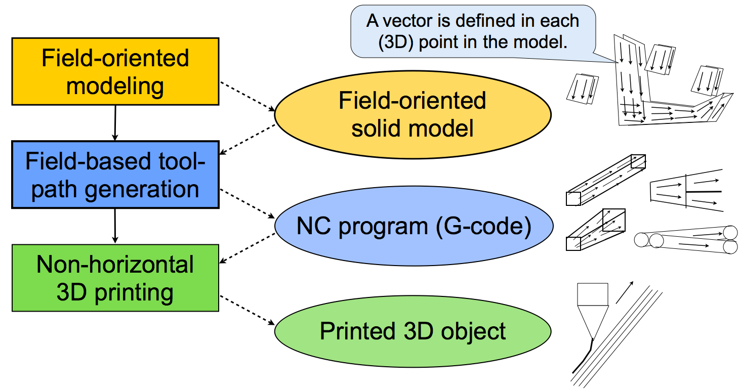
Figure 3. Three steps for natural-direction 3D printing
The field-oriented modeling outputs field-oriented solid model, which is an extension of conventional solid model. A vector is defined at each (3D) point in this model as shown in the figure.
The field-based tool-path generation inputs a field-oriented solid model and outputs a normal NC program, such as a G-code based program. The algorithm of this tool-path generation is completely different from “slicing” algorithms in conventional 3D printing.
By the non-horizontal 3D printing, an object with natural direction is created. This process may be performed by conventional 3D printer because a G-code program can express non-horizontal motions and conventional 3D printers may execute it correctly.
The following three sections explain the above three steps.
3. Modeling Methods
Two methods for field-oriented modeling are proposed here. They are field-oriented 3D CAD and field-oriented 3D painting.
3.1 Field-oriented 3D CAD
Two methods for field-oriented 3D CAD are proposed. One method is “parts combination” shown in Figure 4. In this method, the designer combines 3D parts with “field” using a field-oriented 3D CAD tool. The combination operations are based on normal union, intersection, difference, and so on. However, these operations must define the methods of computing field from the fields in the parts.
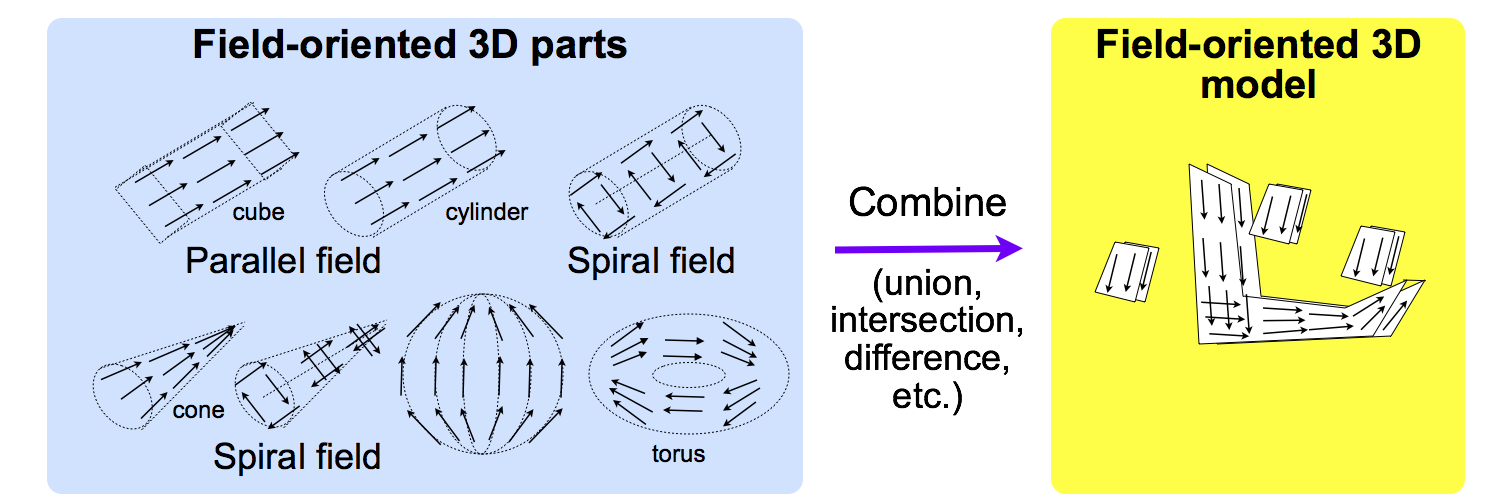
Figure 4. Parts combination in field-oriented 3D CAD
The other method is “magnetization” shown in Figure 5. In this method, the designer first design normal 3D solid model using a conventional 3D CAD tool, and put the object in a field selected by the designer. When the designer specifies “copy field” operation, the field is copied into the object.
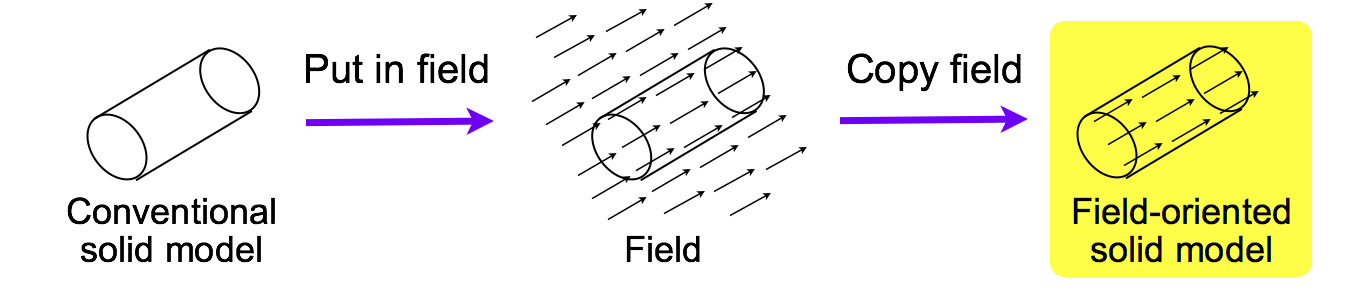
Figure 5. Magnetization in field-oriented 3D CAD
3.2 Field-oriented 3D painting
Field-oriented 3D painting is analogical to 2D painting, which is widely used in personal computers. Similar to a 2D painting tool that uses 2D pointing device, a 3D painting tool uses 3D pointing device (see Figure 6). A human body tracking device, such as Microsoft Kinect, or sensors such as accelerometers used in Nintendo Wii can be used as 3D pointing device. The width and shape of the painting tool (such as 3D brush) can also be specified by human hand (fingers), in the case of a human body tracking, or pressure sensors, in the case of accelerometer-based method. In contrast to normal painting tools, field-oriented 3D painting tools record the direction of motion, and generate field vectors for each point in the painted object.
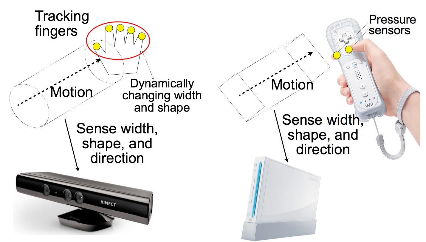
Figure 6. Field-oriented 3D painting
4. Tool-path Generation Methods
A tool path for a 3D printer can be generated using the basic method described in Section 4.1. Several additional techniques are shown in Section 4.2.
4.1 Basic field-based method
In a tool-path generation process, an object is “hashed” along the field vectors as shown in Figure 7. This process is completely different from “slicing” in conventional 3D printing if the field vectors are not in parallel. If the object has parallel field as shown in the left half of Figure 7, the hashed object consists of strings that can be easily filled by constant extrusion of filament. However, if the field vectors are not in parallel, the strings may widening or narrowing as shown in the right half of Figure 7. In these cases, the amount of extrusion should be increased or decreased to fill the string. However, if the vectors are far from parallel, additional techniques are required. Several techniques for handling such situations are described in the next subsection.
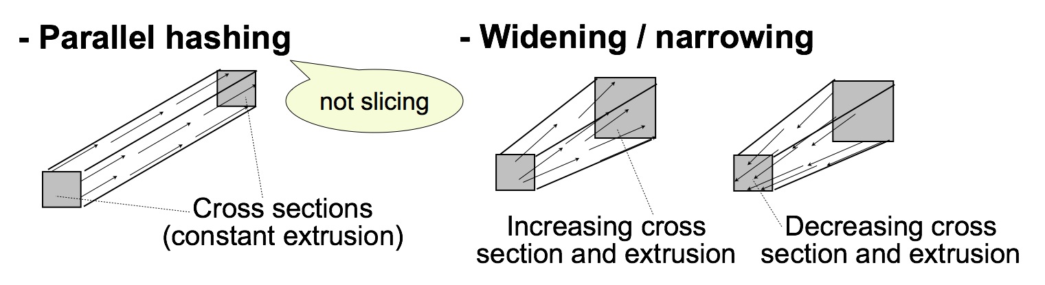
Figure 7. Basic field-based tool-path generation method
4.2 Several techniques
If the cross section of strings change rapidly along the direction, the strings must be split or merged as shown in the left half of Figure 8. The photo included in Figure 8 shows two examples of split/merged object, which was printed by using Printrbot Plus, a 3D printer. If a string is vertically widening and horizontally narrowing, or vice versa, another method called twisting, can be applied (see the right half of Figure 8).
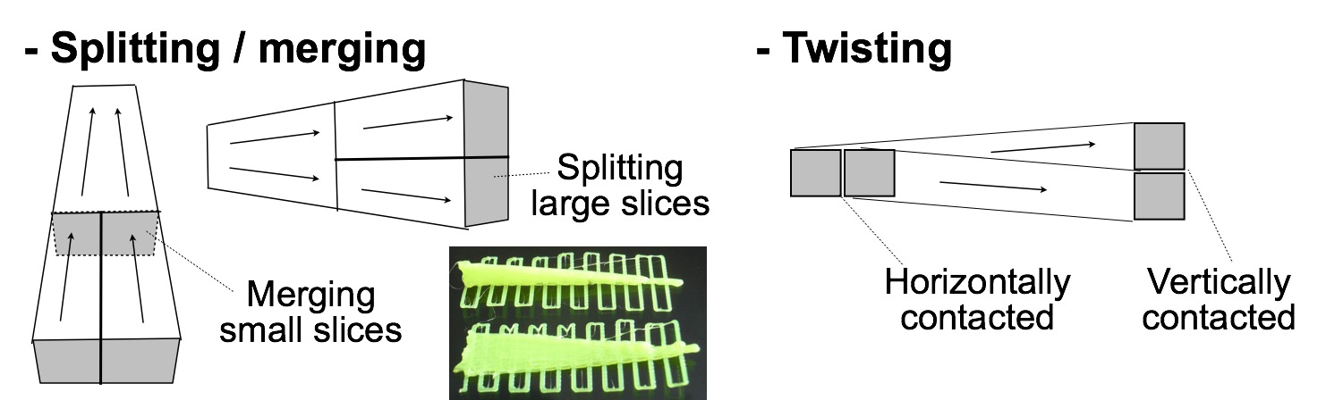
Figure 8. Several techniques in field-based tool-path generation
4.3 Method for making unprintable objects printable
Similar to conventional CNC, some objects are not printable because of their shapes. The range of printable shapes in the natural-direction 3D printing is narrower than that of conventional 3D printing. However, the range can become wider by by changing printing order.
An example is shown in Figure 9. The upper-left figure shows the original shape, a chain with two rings, which is not printable. It becomes printable if one of the rings is divided into two parts and the printing order is changed as shown in the right figure. The photos below shows a rectangle version of this chain, which was printed in natural direction. Because there is currently no tool-path generator, the tool path for this chain was generated by a special-purpose program. The left photo shows the part 3 of this chain.
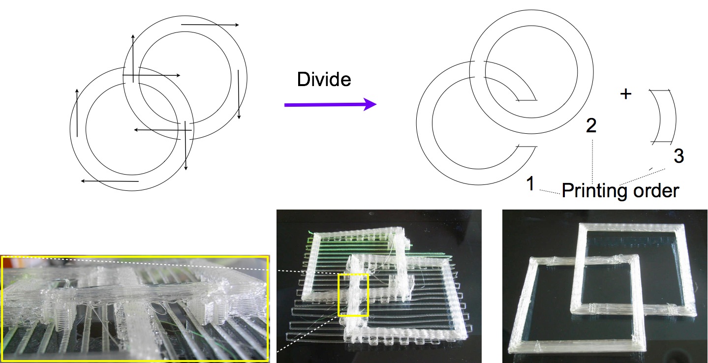
Figure 9. A method for making unprintable objects printable
5. Printing Techniques
Conventional 3D printers accept G-code for natural-direction 3D printing. However, they cannot print steeply. This section describes the problems and printing techniques to avoid it.
5.1 Problems in steep printing
There are two problems that make steep printing difficult or impossible. See Figure 10. One problem is that, because conventional 3D printers are three-axis machines and they extrude only at the bottom, if they print in steep direction, they can collide with printed objects. The nozzle head thus cannot be sufficiently close to printing point. This means there is gap between the nozzle tip and the printing point.
The other problem is that conventional 3D printers can not usually move quickly along z-axis because they usually use threaded rods for z-axis.
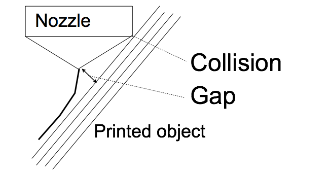
Figure 10. Problem in steep printing
5.2 Two solutions
To solve the first problem, which is much more serious, two methods are available. One method is to use needle-shaped nozzle. The left half of Figure 11 shows this method. If the tip of a nozzle has needle-like shape, it can print in steep angle. However, such as shape of nozzle causes significant decrease of temperature at the tip. Several methods are available to keep the temperature. A method is to cover the tip by insulator as shown in the figure. A needle-shaped nozzle can print in steep angle, but it is difficult for this type of printer to print vertically. However, a printer of this type can be developed by improving a conventional printer.
The other method is to use a five-axis print-head. Two additional axes are used for rotating the head. By rotating a print head, it can print vertically or even at downside. However, a printer of this type must be developed mostly from scratch. Xuan Song et al. [1] developed this type of 3D printer, but the rotation angle is restricted.
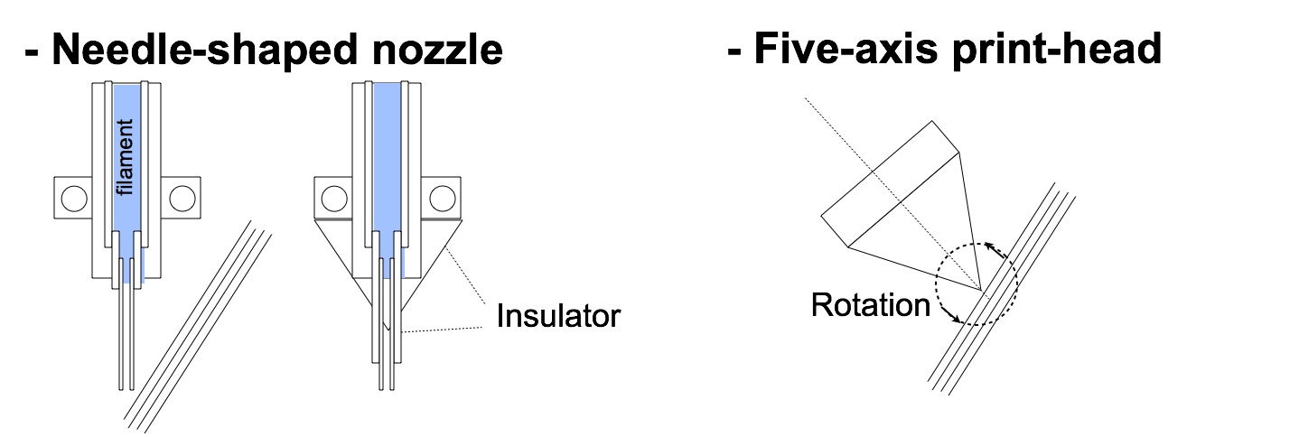
Figure 11. Two solutions to the problem in steep printing
For the solution to the second problem, see Section 6.3.
6. Implementation Status
The implementations of natural-direction 3D printing technologies is in very early stages.
6.1 Field-oriented modeling
A Kinect-based modeler, which is proposed in Section 3.2, is being designed but not yet implemented.
Figure 12. Microsoft Kinect
6.2 Field-based hashing
Only parts of hashing algorithms are being tested. As described in the previous sections, the left photo in the Figure 13 shows testing improvement of printability. The middle photo shows splitting and merging. The right photo shows another test print for 3D calligraphy, which will be explained in the applications section.
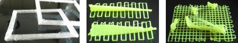
Figure 13. Hashing algorithms tested
6.3 Non-horizontal 3D printing
Non-horizontal printing methods has been tested using Printrbot Plus, and are being tested using Rostock MAX (see Figure 14). Rostock MAX is a Delta type 3D printer that can move its print head quickly along z-axis. Therefore, this type of printers can solve the second problem described in Section 5.1.
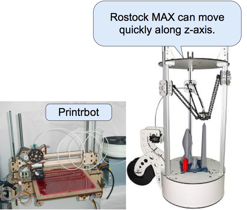
Figure 14. 3D printers used for testing the printing method and techniques
7. Applications
3D printing has been used for industrial applications, especially for rapid prototyping. However, major applications of natural-printing technologies may be different types of applications.
7.1 Art: 3D calligraphy
Natural direction may be more important in artistic applications. This subsection focuses on applications to 3D calligraphy. The left half of figure 15 shows (mostly) non-directed 3D calligraphy arts. The right half shows directed 3D calligraphy arts. Natural-direction printing can be applied to directed 3D calligraphy, but it has not yet applied. There are some work in iron based directed 3D calligraphy. This figure shows work of Shishu, a Japanese calligraphy artist.
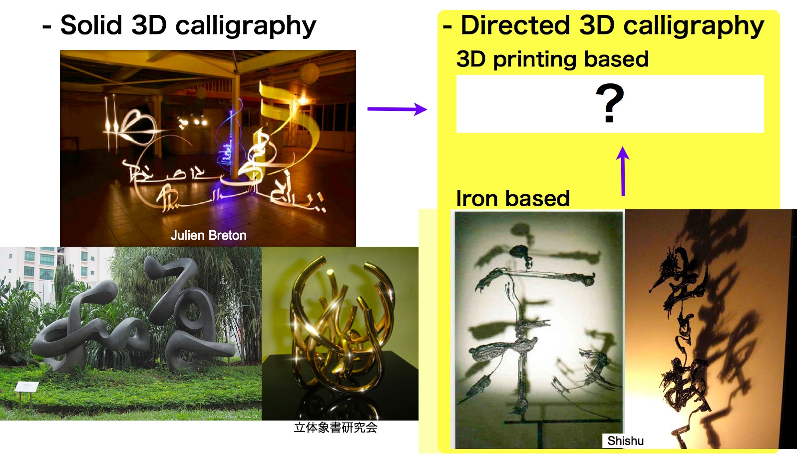
Figure 15. 3D calligraphy application
7.2 Hobby
Recently, a cheap FDM 3D printers are used by hobbyists. A pyramid or a polyhedron shown in Figure 16 may be printed better by using natural-direction printing methods.
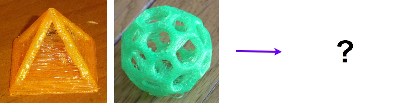
Figure 16. Hobby application
7.3 Industrial applications
There may be industrial applications (see Figure 17), but promising applications are not known.

Figure 17. Industrial applications?
8. Concluding Remarks
This presentation can be summarized as follows.
- Natural direction of 3D objects can be expressed by FDM 3D printing using field-oriented/based modeling, hashing, and printing methods.
- The developments of field-oriented/based algorithms and applications are in early stages.
The field-oriented modeling, the field-based tool-path generation methods, and non-horizontal 3D printing methods are going to be developed, and they are applied to the applications, especially to 3D calligraphy at first.
References
[1] Xuan Song, Yayue Pan, and Yong Chen, “Development of a Low-Cost Parallel Kinematic Machine for Multi-Direction Additive Manufacturing”, SFF Symposium 2013.
